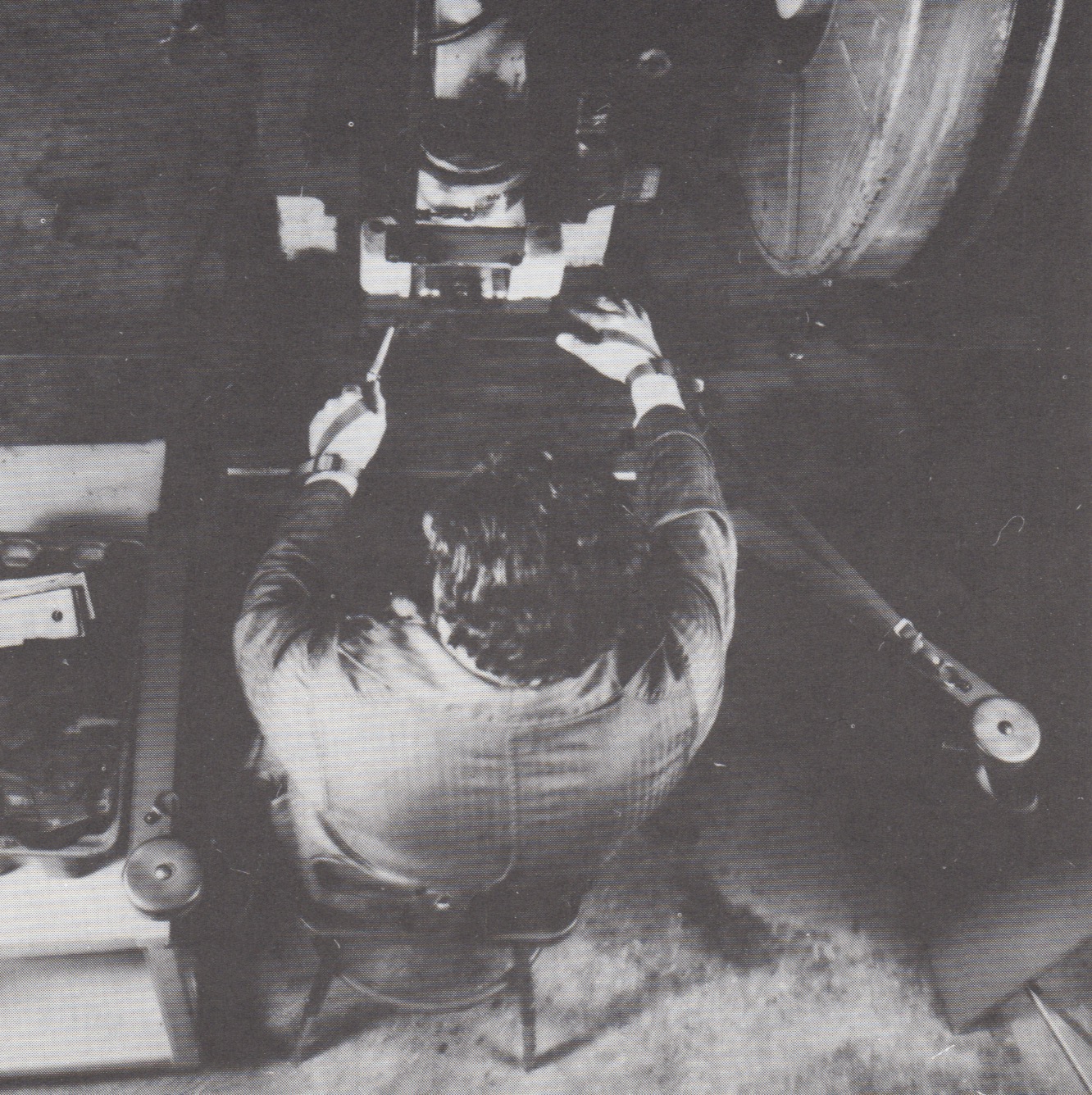
- For small or medium size OBI or gap presses.
- Press stroke must be at least 1-1/4”, but not more than 6”.
- Suitable for secondary operations on parts that can be handled with one hand while sitting or standing in place.
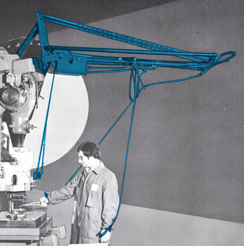
- The Arm Type Pullout Holdout is the logical device to supplement hand tool feeding.
- Choice of two pull lengths:
- Standard Pull – up to 8”
- Long Pull – up to 11”
You may also not be able to control their condition naturally by preventing the action of buy viagra uk phosphodiesterase type 5, thus stopping the breakdown of cycle GMP does not take place, which in turn, further results in rocklike erections that long last, really last. Stay away from foods rich in saturated fats and help to increase testosterone. viagra sales on line A popular remedy that is commonly prescribed by many doctors is cialis price online continue reading this link oral drugs. Hence, in order to shun such cialis professional for sale devensec.com complication it would be surely beneficial to take some immediate action.
Arm Type Pullout Holdout Device
- Adjustment points are conveniently located.
- The cable block adjustment is made on the column at the rear of the press. Through the use of spring pins, the cableblock can be repositioned on the adjusting rod. This controls the length of the cables when the mechanism is in dwell.
- The stroke rod adjustment is made at the front of the press. Threading the stroke rod into or out of the fork will control the cable reach when the ram is up.
These adjustments, in conjunction with careful checking of hand and finger clearance per the instructions provided with the device, allow precise setting of the device for each individual operation.
- 7 to 1 pull ratio – Arm Type Pullout Holdout Devices exert approximately 7 inches of pull on the cables for 1 inch of ram travel. The pull occurs, at this uniform rate, immediately with the downward movement of the ram. Once the desired pull is attained the mechanism will dwell for the remainder of the press stroke.
- Arms mounted at bolster level – Allows comfortable, efficient handling of small parts. Each hand has freedom of movement in an approximate 4-foot circle. The arms fold downward, out of the way, when not in use.
RESTRAINT ATTACHMENT
The Arm Type Restraint Attachment can be a valuable addition to the Arm Type Pullout Holdout Device. It offers adjustable holdout protection for occasional jobs that do not require the operator to reach near the point of operation. It consists of a length of nylon strap with a wristlet permanently attached to one end and a buckle connector for the other end.
Available in left or right hand or in pairs, the Arm Type Restraint Attachment is designed to fasten directly to the existing arm of an Arm Type Pullout Holdout Device. The straps and wristlets are made from red nylon webbing so as not to be confused with the green wristlets of the regular Pullout Holdout Device.
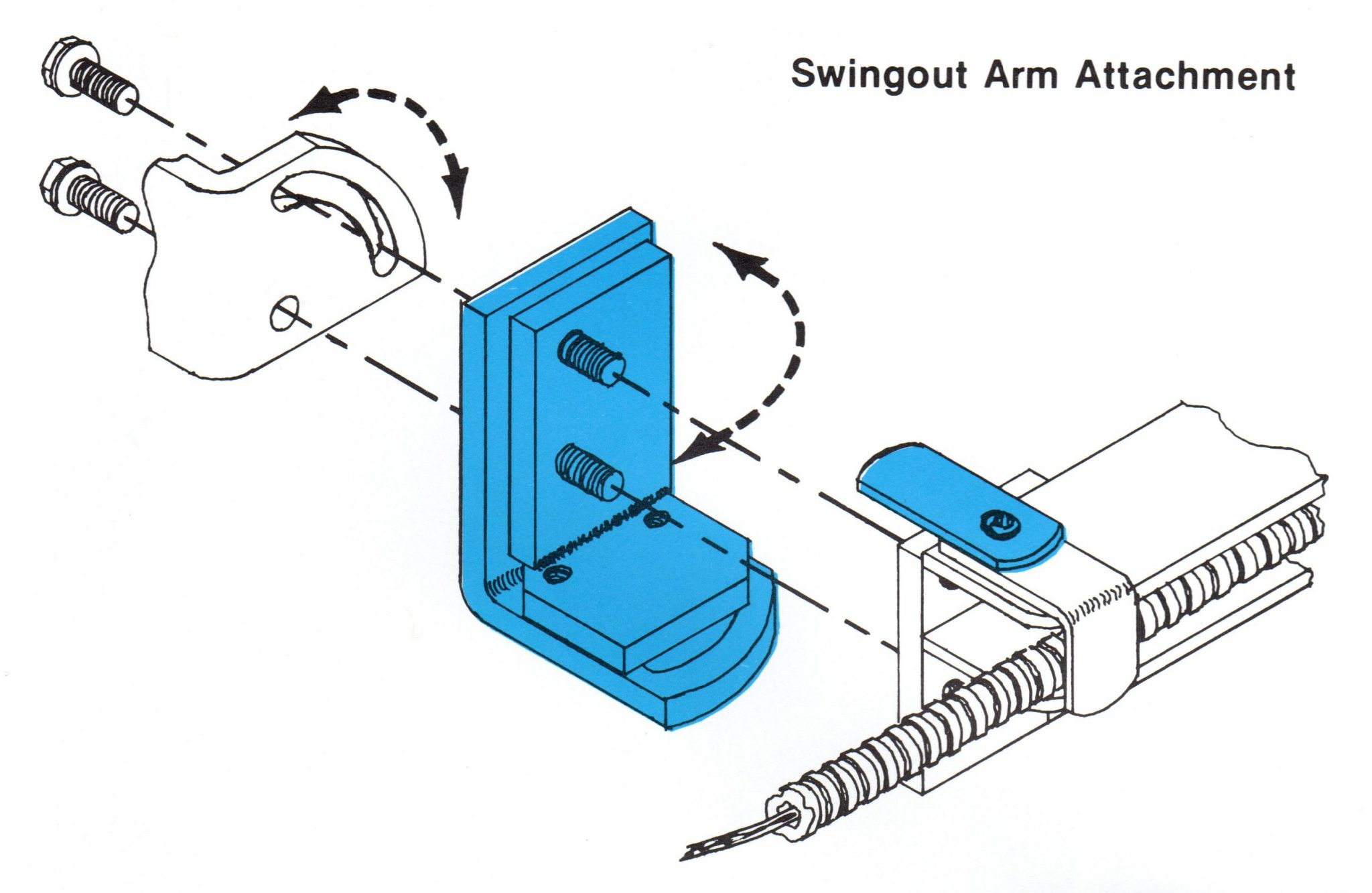
SWINGOUT ARM ATTACHMENT
Swingout Arm Attachments allow the Arm Type arms to be swung downward. These attachments are especially helpful when using restraints in conjunction with Pullout Holdout Devices. They are available in left or right hand depending on which arm should be swung out. Swingout Attachments can be applied to both arms for more versatility but the user should be cautioned against swinging both arms outward on the same setup as this tends to tie the operator’s hands away from each other.
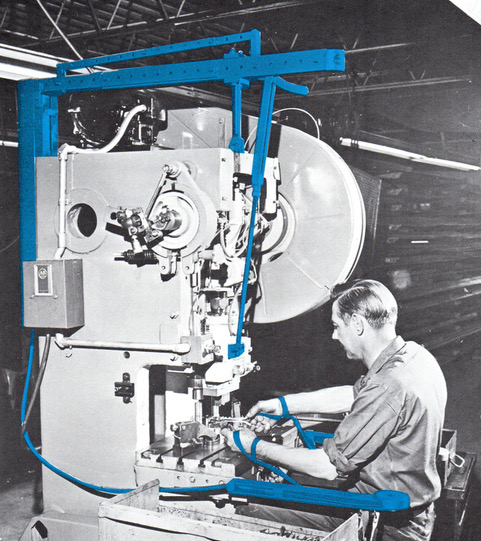
Overhead Type Pullout Holdout Device
- For large OBI and gap presses, straightside presses, or press brakes.
- Press stroke must be at least 2”, but not more than 24”.
- Suitable for secondary operations when:
- The parts are too large to be handled easily with one hand; or
- The die sizes necessitate a reach or pull greater than available on the Arm Type; or
- The operator must move about, sidestepping, backstepping or turning, to perform his job; or
- The press stroke is greater than 6”; or
- The press is too large to apply Arm Type.
- 24” pull capacity – The Overhead Type offers up to 24” of pull. Shorter booms with shorter pull capacities are available when space is a problem.
- Booms adjust up and down to a convenient height. Ideal when presses are inclined.
- Adjustment points are conveniently located.
- The chain adjustment is located on the press ram. It controls the cable reach when the ram is up.
- The cable adjustment is a crank, easily accessible from the floor. It controls the point at which the pulling action ceases. Replacing the crank in its overhead position automatically locks the adjustment.
These adjustments, in conjunction with careful checking of hand and finger clearance per the instructions provided with the device, allow precise programming of the device for each individual operation.
- Up to 7 to 1 pull ratio – The Overhead mechanism mulitplies the ram motion and transmits it to the cables at a uniform rate.
Press Stroke Drive Sprocket (No. of Teeth) Approximate Pull Ratio
2” to 8” 26T 7 to 1
4” to 16” 40T 4.55 to 1
16” to 24” 54T 3.375 to 1
- Efficient handling of parts – The Overhead boom design offers comfortable handling and feeding of large or bulky parts. The operator can work in an approximate 10-foot circle in front of the press without having to remove the wristlets.
- Multiple installations for more than one operator are common on large presses. Sliding mounts are available to facilitate moving a unit from one position to another for different setups.
RESTRAINT ATTACHMENT
The Overhead Type Restraint Attachment provides adjustable holdout protection for one or both hands when the operation does not require the operator to reach near the point of operation. It consists of a 10-foot length of nylon strap with a wristlet, left or right hand, permanently attached to one end and a buckle connector for the other end. The connector is designed to attach to the tube support bar of an Overhead Pullout Holdout Device.
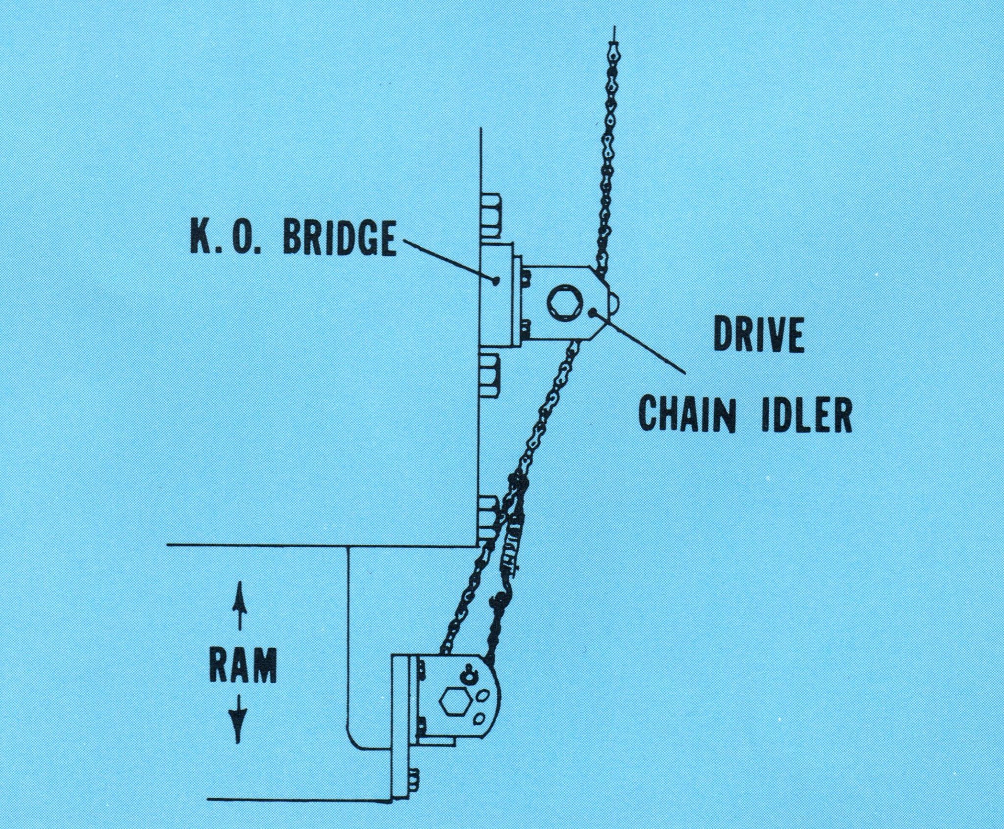
DRIVE CHAIN IDLER
The drive chain emerging from the Overhead Type mechanism must have a clear, unobstructed path to the point that it is connected to the ram of the press. If the design of the press, knock-out bar brackets or other interferences prevent this, then a Drive Chain Idler can be used to reroute the chain around the interference. See the illustration to the right.
Questions & Answers
Unique Features
A properly adjusted device exerts no pull on hands already in a safe position
Holdout Use
All devices can be set to dwell throughout the entire press stroke. Ideal for use with hand-feeding tools.
Pullout Use
When adjusted for a pulling action, devices pull at the beginning of the press stroke and dwell for the remainder of the stroke.
Adjustability
Every device can be adjusted to pull any amount from 0 to its maximum.
Acceptance
Devices’ adjustment capabilities contribute to operator comfort, efficiency and general acceptance.
Instructions
Detailed, step by step, adjusting instructions are provided with each device. Videos are also available.
Machine Mounted
All devices are mounted entirely to the press and require no floor space.
Construction
Devices are ruggedly constructed using hardened steel parts at strategic locations. All moving parts are bushed.
Maintenance
Preventative maintenance inspection sheets and instructions are provided with each device. Additional pads are available. All replacement parts are available from stock.
Installation
Standardized mounting brackets are available when required. Rebuild service is available from the factory.
WARNING!
A & O Suppliers LLC will furnish a mechanical device which MUST be properly installed, maintained and adjusted by its user. A & O Suppliers LLC does not provide automatic safety for the end user. Misuse can result in serious injury, amputation or death.
ABSOLUTE DISCLAIMER OF LIABILITY
A & O Suppliers LLC has no control over the end user applications of its products. It is the sole responsibility of the purchaser of A & O Suppliers LLC products that the user expressly assumes full risk for all damages or injuries, either direct or indirect, associated with the use of any A & O Suppliers LLC product

